Instructions:ShopBot 3-Axis CNC Mill: Difference between revisions
Ttenbergen (talk | contribs) No edit summary Tag: Manual revert |
Ttenbergen (talk | contribs) m Ttenbergen moved page Instructions:ShopBot 3-Axis CNC Mill Model to Instructions:ShopBot 3-Axis CNC Mill without leaving a redirect: Text replacement - "ShopBot 3-Axis CNC Mill Model" to "ShopBot 3-Axis CNC Mill" |
(No difference)
| |
Revision as of 22:35, 2024 August 10
Want to learn about Aspire? See Instructions:Aspire

for all |
Want to make this page better? Edit it yourself, or talk to John Hache. North Forge would like to make sure instructions are clear and easy to use. |
Safety
Fire Notice
DANGER: FIRE. The ShopBot vacuum and dust extractor make it difficult to notice a fire until it has already started spreading. Always carefully plan cuts and monitor jobs closely.
If you notice any of the following:
- Burning smell
- Charring
- Tool damage
- Unusual Vibration
- Change in sound
STOP AND INSPECT THE DUST COLLECTOR FOR SIGNS OF FIRE. More details to follow here.
PPE
Wear:
- Safety Glasses (to protect against flying dust and debris).
- Hearing protection (to protect against noise greater than 85 dBa).
- Respiratory Protection (N95 dust mask or respirator) to protect against airborne dust when cleaning or running the equipment.
Hazards
| Hazard | Causes | Mitigation | |
|---|---|---|---|
| Fire | Friction from tools, improperly installed tools | Use correct feeds and speeds
Make sure the tool sticks out far enough Do not leave the ShopBot unattended |
|
| Projectiles | Workpiece shattering
Tool shattering Tool slipping Collision with fixtures and clamps Debris in wood |
Check for cracks, knots, and debris in wood
Clean tool holder with compressed air Program file to avoid collisions Check that actual home position matches programmed home position |
|
| Entanglement | Pinch points
Rapidly moving automatic equipment |
No loose hair, clothing, earbuds, hoodie strings, etc
|
|
| Noise | Motor noise, vacuum noise, tooling noise | Wear hearing protection | |
| Inhalation | Airborne dust | Wear dust mask or respirator (minimum N95) while operating and cleaning |

E-STOP
In case of emergency, stop the ShopBot using one of three methods:
- E-STOP button on the remote. This will immediately cut all power to the ShopBot. The tool will spin down naturally. E-STOP is a good default option.
- Press the Spacebar. This will lift the tool up and apply the brake. This is a good option in less urgent situations, like needing to adjust the zero positions.
- Click the mouse. When the job starts, the mouse will automatically lock onto the stop button. Pressing any button on the mouse will stop the job in the same way as the spacebar.
Common Problems
Most issues are caused by:
- Improper feeds and speeds
- Improper tooling
- Improper fixturing
- Improper programming/setup (offset mistakenly applied, not setting zeroes consistent with the programming, not avoiding fixtures)
Housekeeping
Empty the dust collector when the dust has piled halfway up the viewing window.
Break down large pieces before putting them garbage bins. Blunt sharp corners to avoid puncturing the bag and injuring the person carrying it.
After use, clean the equipment and surrounding area:
- While wearing respiratory protection, use compressed air to clean the gantry. Focus on areas where parts interact: rack and pinion, spindle mount, motor mounts, etc.
- Clean the floor using a broom and dustpan, shop vacuum, or the dust collector hose. Replace the dust collector hose when done.
- Empty any garbage bins that are more than 75% full and replace the bag.
- Empty the dust collector if required.
- Return fab lab tools to their proper locations:
- Tool holders on the rack
- Collets in the drawer
- Collet wrench placed beside locking fixture
- Calipers, drills/impact drivers, squares, hand tools in the tool room
- Remove any personal tools, materials, and removable media from the room. The workbench should only have the wrench and locking fixture on it when done. Due to local fire code, do not store stock materials in the CNC room (fixtures are OK - label with name and phone number)
- Turn off the equipment per shutdown procedures.
- Turn off the dust collector. If you are the last one in the room, turn off the room exhaust. The room exhaust is interlocked to the electrical system; turning off the room exhaust will turn off all equipment in the room.
Workholding Policies
Most profile cuts will cut entirely through the workpiece and into the spoilboard below. In order to cut all the way through the material without unnecessarily damaging the spoilboard, North Forge suggests programming cuts using the following formula:
Depth of Cut = Stock Thickness + 0.01”
Always measure stock thickness with calipers, never with tape measures or nominal dimensions.
If your cut penetrates deeper than 0.06” into the spoilboard, please stop and investigate. If the stock is set up correctly and the depth of cut is appropriate, the collet may be dirty or damaged and the tool slipping out, or the secondary spoilboard may not be perfectly parallel to the gantry (for example due to debris between the primary and secondary spoilboard).
SCREWS
When using North Forge’s secondary spoilboard, it is okay to screw the workpiece in place. Do not screw into the main vacuum spoilboard. Do not use excessively long screws (ie long enough to pierce both the secondary spoilboard and the vacuum spoilboard).
SPRAY ADHESIVE METHOD
It is also possible to use spray adhesive to secure the entire workpiece to the secondary spoilboard.
- Cover both the bottom of the workpiece and the appropriate part of the spoilboard with masking tape or painter’s tape.
- Spray both surfaces with spray adhesive.
- Press the two surfaces firmly together and hold for 30 seconds.
- Test the hold by trying to move the workpiece sideways.
Other
Other workholding arrangements are possible, including vices, pins, clamps, custom fixtures, and the vacuum system.
If you are cutting all the way through a large workpiece on the vacuum spoilboard, BE CAREFUL. There is a high risk of damaging the vacuum spoilboard. It’s a good idea to test cut settings on a small workpiece and a secondary spoilboard.
The primary goal of workholding is to control the movement of the workpiece in three axes: X, Y, and Z. Always carefully check toolpaths to ensure they will not collide with any fixturing.
TIP: After a cut operation, the ShopBot will move to the “Z Safe height” before moving rapidly to its next position. When using clamps or other fixturing, adjust the Z Safe Height in the CAM software such that the Z safe height is above the clamp or fixture.
Pre-Use Checklists
Safety
- PPE (hearing, eye, respiratory protection) is correctly used and in good condition
- Loose hair, clothing, and accessories have been removed or secured
File
- Programmed feeds and speeds are appropriate for the tool, material, and cut type
- File is programmed to avoid colliding with fixtures and equipment
- Files have been copied from portable media to the working computer
Stock Setup
- Physical origin (home position) is set to the same point as programmed (X, Y, and Z)
- Stock is facing the correct direction per the program
Tool
- Collet and tool holder have been cleaned; tool is secure
- Tool stickout is long enough to complete the cut (tool holder will not collide with the top of the workpiece)
- Tooling is sharp
- Tooling is appropriate for the task (not using downcut or compression end mills for drilling holes, not using standard low-RPM twist drills for drilling, etc)
Workholding
- Workpiece is secured to the table
- Hold has been tested by manually trying to move the workpiece.
- Screws are long enough to secure the material (4-5 teeth protrude into secondary spoilboard)
- Workpiece is secured in accordance with NF policies (no screws or glue on vacuum spoilboard)
Final checks
- Workpiece has been inspected for hidden debris (nails, stones, etc)
- Table is clear of tools and unused materials
- Spindle RPM has been verified
- Dust collector is on, emptied if necessary, and hose is connected
WARNING: UNEXPECTED HAZARDS. Stop cutting immediately if:
- Workpiece, cutter, or equipment is vibrating excessively
- The sound of the spindle or cut changes unexpectedly
- Through cuts penetrate the workpiece in fewer cuts than expected
- Signs of fire appear (smell of smoke, visible charring, embers).
Operations
Instructions and proper formatting will follow.
Room Layout
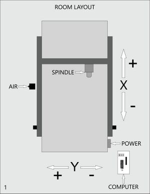
Pay attention to the axis system when programming. Maybe some text will fix the formatting.
Vacuum Zones
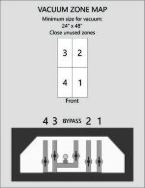
The vacuum table has four zones. Open the valves for the zones that you are using. Close the valves for the zones that you are not using.
Setup
1. Turn on the room exhaust.
2. Turn on the computer.

3. Turn on the air.
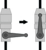
4. Reset the E-STOP.
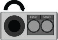
5. Turn on the ShopBot power (right side of machine).

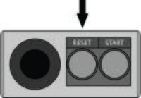
6. Press RESET on the remote.
7. Start ShopBot 3 Software
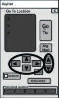
8. Open the Key Pad

9. Use the arrow keys to move the head around
- On the keyboard: use the arrow keys for XY movement, Page UP/Page DOWN to move Z axis
- On screen: use the arrow buttons to manually move the head, or type the destination location and use GOTO
10. Load the spoilboard and/or material.
11. Start the vacuum table per vacuum table instructions.
Vacuum Table
1. Clean the table of debris (wear respiratory protection if using compressed air). Debris can affect part accuracy.
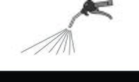
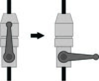
2. Open all valves on the vacuum table (OPEN = valve handle parallel to pipe)

3. Turn on the vacuum table using the remote outside the room.
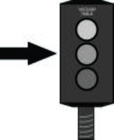
4. Close the BYPASS valve (middle) and any unused zones.

5. Check the hold by pressing horizontally on the secondary spoilboard or workpiece.
Tool Holder
Assembly
1. Clean components with compressed air.
- Debris caught in the tool holder can cause the tool to slip, damaging the tool and equipment.
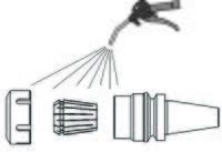
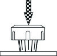
2. Insert the collet into the nut.
- Put the collet on the table and the nut on top.
- Press on the nut until the collet snaps in place.
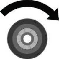
3. Screw the collet loosely into the holder.
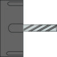
4. Insert the tool.
- Do not tighten on the flutes
- Make sure enough of the shank is in the collet to properly hold the tool - tool should fill ~80% of the length of the collet.
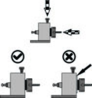
Load the collet into the fixture:
- Press and hold the top knob
- Insert the holder; rotate and push until it's fully inserted
- Shoulder must be flush with the face of the fixture
5. Tighten the collet nut.
- Ensure all four teeth on the wrench are engaged
- Tighten the nut until the table lifts from the floor
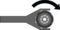
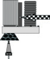
6. Load the tool into the ShopBot
- Support the holder from the bottom
- Tool goes into the conical receptor under the skirt
- Press the green button briefly until the tool gets sucked in
- If the tool is not sucked in, blow off the beige control box near the pillar with the air line.
Disassembly
1. Unload the tool from the ShopBot.
- Support the tool holder from the bottom
- Press the green button; tool holder will fall out
2. Unscrew holder and remove collet and nut.
- Load the tool holder into the fixture
- Use the wrench to unscrew the nut
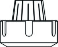
3. Remove the collet by pushing with thumbs.
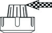
4. Replace the collet, nut, and tool holder on the shelf.
Zeroing Axes
XY Zero
XY axes are set manually (moving the tool to the desired home position).
1. Open the Key Pad.

2. Use the arrow keys to move the head to the desired home point.

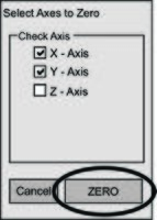
3. Select ZERO AXES.
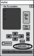
4. Check "X-Axis" and "Y-Axis" then press ZERO
Z Zero
Z zero is done automatically with the Z zero routine.
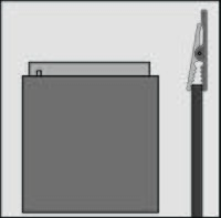
1. Attach the Z zero fixture.
- Attach the clip to the collet nut or the tool
- Place the plate on the spoilboard or the top of the material, depending on how your file was programmed
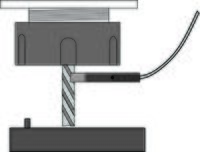
2. Check the connection for continuity.
- Lift the plate and tap it against the tool. If input #1 flashes on screen, the connection is good. If input #1 does not flash, adjust the clip and retry.
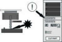
3. Run the Z zero routine
- Tool will tap twice against the plate
- Watch the Z axis readout: if it continues scrolling downwards without stopping, the ShopBot has not detected the end of the tool. You must stop the routine and try again.

4. Remove and store the fixture.
- Plate goes in the 3D printed holder
- Clip attaches to the frame
- Make sure the clip is not touching the plate
Spindle RPM Check
Occasionally, the ShopBot does not read the RPM from the file correctly. Other users may also have adjusted the default RPM away from 18,000. Use this method to manually enter the RPM.
1. Select Tools, then Spindle RPM Control

2. Click to the left of the word PREVIEW
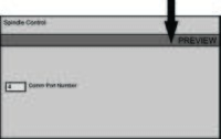
3. Type the desired RPM and hit ENTER
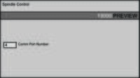
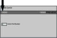
4. Cursor automatically moves left. Type the RPM again and hit ENTER.
Running a Job
- If you're not already wearing PPE (hearing protection, safety glasses, respiratory protection) put it on now.
1. Check the dust collector. If the dust is halfway up the viewing window, empty it before use.
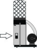
2. Transfer files from USB to the computer. The ShopBot will not be able to read the files if they are left on the USB stick.

3. Select CUT PART on screen and open the cut file.

4. Press START on screen. Ignore the yellow file information screen that pops up.

5. DO NOT PRESS OKAY - warning screen will appear.
- Pressing OK without starting the dust collector and spindle will damage the equipment!

6. Turn on the dust collector.
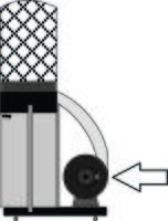
7. Start the spindle using the START button on the remote.
- Listen to make sure the sound is appropriate
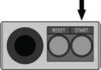
8. Press OK on screen.
- The job will start
- Keep your hand on the space bar, mouse, or E-STOP

Shutdown
1. Turn off the dust collector. Empty it if the dust is more than halfway up the viewing window.

2. Shut down the vacuum table.
- Open all valves
- Wait 5 minutes for the motor to cool
- Shut off using the remote outside the room

3. Remove the tool from the head.

4. Move the head to the front of the bed.

5. Install the rest block under the head.
- Make sure the skirt isn't resting on the support block.
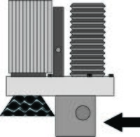
7. Turn off the power.

8. Turn off the air.
- The head will slowly sink downwards onto the rest block.
9. Turn off the exhaust if you are the last one in the room.
- If the air is visibly dusty, you may need to leave the exhaust running until it clears.
- Turning off the exhaust will cut power to other equipment in the room!
